Home /
Answered Questions /
Other /
google-this-question-involves-designing-a-simple-rc-band-pass-filter-the-basic-circuit-to-be-used-is-aw570

(Solved): ... Google This Question Involves Designing A Simple RC Band-pass Filter. The Basic Circuit To Be Us...
Please explain clearly
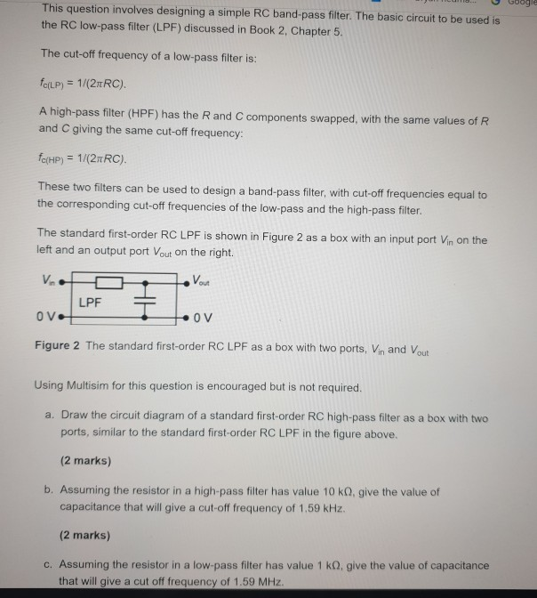
... Google This question involves designing a simple RC band-pass filter. The basic circuit to be used is the RC low-pass filter (LPF) discussed in Book 2, Chapter 5. The cut-off frequency of a low-pass filter is: forLP) = 1/(2TRC). A high-pass filter (HPF) has the R and C components swapped, with the same values of R and C giving the same cut-off frequency: fc(HP) = 1/(2nRC). These two filters can be used to design a band-pass filter, with cut-off frequencies equal to the corresponding cut-off frequencies of the low-pass and the high-pass filter. The standard first-order RC LPF is shown in Figure 2 as a box with an input port Vin on the left and an output port Vout on the right. Vio -Von LPF OV OV Figure 2 The standard first-order RC LPF as a box with two ports, Vin and out Using Multisim for this question is encouraged but is not required. a. Draw the circuit diagram of a standard first-order RC high-pass filter as a box with two ports, similar to the standard first-order RC LPF in the figure above, (2 marks) b. Assuming the resistor in a high-pass filter has value 10 ko, give the value of capacitance that will give a cut-off frequency of 1.59 kHz. (2 marks) c. Assuming the resistor in a low-pass filter has value 1 kg, give the value of capacitance that will give a cut off frequency of 1.59 MHz.
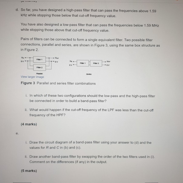
d. So far, you have designed a high-pass filter that can pass the frequencies above 1.59 kHz while stopping those below that cut-off frequency value. You have also designed a low-pass filter that can pass the frequencies below 1.59 MHz while stopping those above that cut-off frequency value. Pairs of filters can be connected to form a single equivalent filter. Two possible filter connections, parallel and series, are shown in Figure 3, using the same box structure as in Figure 2 OV View larger image Figure 3 Parallel and series filter combinations i. In which of these two configurations should the low-pass and the high-pass filter be connected in order to build a band-pass filter? ii. What would happen if the cut-off frequency of the LPF was less than the cut-off frequency of the HPF? (4 marks) i. Draw the circuit diagram of a band-pass filter using your answer to (d) and the values for R and C in (b) and (c). il Draw another band-pass filter by swapping the order of the two filters used in 0. Comment on the differences (if any) in the output. (5 marks)
We have an Answer from Expert
View Expert Answer
Expert Answer
Question (a) The circuit of a first order high pass filter is shown below Question (b) Given Question (c) Given Question
We have an Answer from Expert
Buy This Answer $6
Buy This Answer $6
-- OR --
Subscribe To View Unlimited Answers
Subscribe $20 / Month
Subscribe $20 / Month